First Software Configuration
ソフトウェアインストール後の初回起動時に、1Clickソフトウェア構成が表示されます。この初期構成はガイドに従って行われます。この構成を行うことで、すぐにスキャンを実行し、ファイルを送信できるようになります。
Contents
構成ファイルの設定
このプロセスの最初のステップでは、スキャナーの構成ファイルを設定します。構成ファイルにはユーザーが使用するスキャナーのさまざまなコンポーネントに関するすべての情報が含まれるため、この設定はシステムの正常動作に必須です。
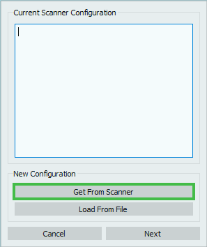
設定するには、スキャナーが正しく接続されていて電源が入っていることを確認し、Get From Scanner(スキャナーから取得)ボタンを押すと、自動的にロードされます。
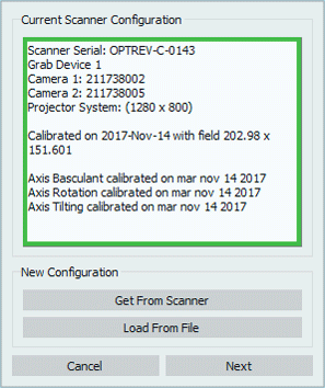
ファイルが正常にロードされると、ボックス内に以下が表示されます。
- スキャナーのシリアル番号
- スキャナーのコンポーネント
Load From File(ファイルからロード)ボタンを使って、外部ファイルから構成をロードすることも可能ですが、この操作が必要になるのは非常に希なケースです(オープンテクノロジー社側でスキャナーの構成ファイルを編集する必要があり、内部ファイルが有効でなくなった場合など)。
ダイアログでNextボタンをクリックし、構成を進めます。中止する場合は、Cancelボタンをクリックします。
システムのキャリブレーション
以下の手順でシステムのキャリブレーションを実行します。光学ヘッドをキャリブレーションしてから、駆動システムのキャリブレーションを行います。
Head Calibration
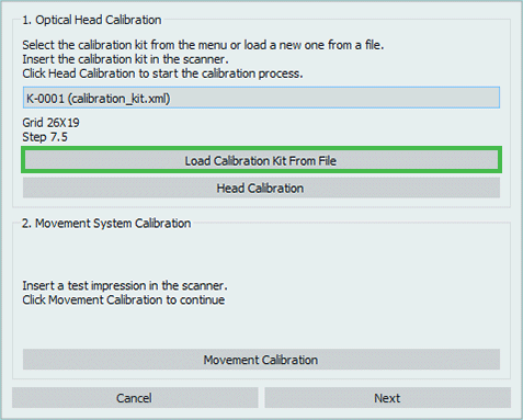
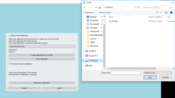
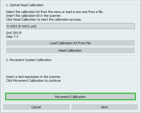
In order to proceed, the calibration kit .xml file must be loaded, by clicking on the buttonLoad Calibration Kit from File.
This .xml file can be found in the scanner's internal memory, identified by the computer as if it were a Usb flash drive.
NOTE: CHECK THAT THE NUMBER OF THE FILE AND THE NUMBER OF THE PLATE YOU HAVE IN THE ACCESSORIES BOX COINCIDE. IF THEY DO NOT CONTACT YOUR DEALER BEFORE CALIBRATING
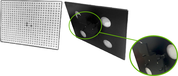
To insert the calibration plate in the scanner, detach the black support on the back of the plate simply by pulling, as it is held by magnets.
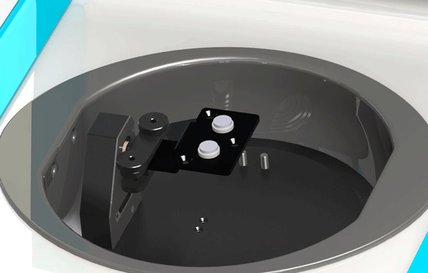
Release the two screws of the impression holder and insert the master support, tightening the screws as much as possible to fix it properly.
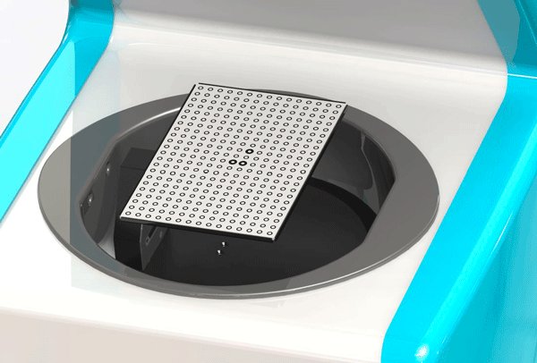
Place the calibration plate in the scanner taking care in positioning it keeping the part with one bold dot on the left and the side with two bold dots on the right.
Click the button Head Calibration to start calibration.
Movement System Calibration
To follow with the movement system calibration insert an impression in the scanner as shown in the image and click on the button Movement Calibration
Click next in the dialog to follow with the configuration, click Cancel to abort.
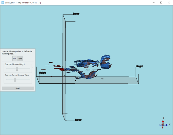
Set the Trimming
In this step the user can configure an automatic trimming that will automatically erase all the information located under the scan height plane.
Move the slider on the bar in the dialog to modify the scan height, taking particular care in not colliding with essential parts of the impression.
Click next in the dialog to end the first configuration procedure.
