Difference between revisions of "Software Configuration"
(→Head Calibration) |
(Marked this version for translation) |
||
| (8 intermediate revisions by 2 users not shown) | |||
| Line 1: | Line 1: | ||
| − | {{DISPLAYTITLE:First Software Configuration}} | + | {{DISPLAYTITLE:First Software Configuration|NOERROR}} |
<translate> | <translate> | ||
| + | <!--T:1--> | ||
With the first launch of the software after installation comes the configuration of the 1Click software. This first configuration is fully guided and will allow the user to be operative scanning and sending files in just a couple of minutes. | With the first launch of the software after installation comes the configuration of the 1Click software. This first configuration is fully guided and will allow the user to be operative scanning and sending files in just a couple of minutes. | ||
| − | =Setting the Configuration File= | + | =Setting the Configuration File= <!--T:2--> |
| + | <!--T:3--> | ||
The first step of the process allows to set the configuration file of the Scanner. The Configuration file holds all the information on the various components of the user's specific scanner, therefore it is crucial for the functioning of the system. | The first step of the process allows to set the configuration file of the Scanner. The Configuration file holds all the information on the various components of the user's specific scanner, therefore it is crucial for the functioning of the system. | ||
| + | <!--T:4--> | ||
[[File:LoadConf.PNG]] | [[File:LoadConf.PNG]] | ||
| + | <!--T:5--> | ||
To set it, make sure that the scanner is correctly connected and switched on and click on the '''Get From Scanner''' button to load it automatically. | To set it, make sure that the scanner is correctly connected and switched on and click on the '''Get From Scanner''' button to load it automatically. | ||
| + | <!--T:6--> | ||
[[File:LoadedConf.PNG]] | [[File:LoadedConf.PNG]] | ||
| + | <!--T:7--> | ||
Once the file has been succesfully loaded, in the box will be shown: | Once the file has been succesfully loaded, in the box will be shown: | ||
*the scanner's serial number | *the scanner's serial number | ||
*the scanner's components | *the scanner's components | ||
| + | <!--T:8--> | ||
It is also possible to load a configuration from and external file, using the button ''Load From File'', though this kind of operation will be performed in very rare cases (for instance if Open Technologies had to modify the configuration file of the scanner and the internal file is no longer valid). | It is also possible to load a configuration from and external file, using the button ''Load From File'', though this kind of operation will be performed in very rare cases (for instance if Open Technologies had to modify the configuration file of the scanner and the internal file is no longer valid). | ||
| + | <!--T:9--> | ||
Click next in the dialog to follow with the configuration, click Cancel to abort. | Click next in the dialog to follow with the configuration, click Cancel to abort. | ||
| − | =System Calibration= | + | =System Calibration= <!--T:10--> |
| + | <!--T:11--> | ||
The following step is the System Calibration starting with the Optical Head and then calibrating the movement system. | The following step is the System Calibration starting with the Optical Head and then calibrating the movement system. | ||
| − | ===Head Calibration=== | + | ===Head Calibration=== <!--T:12--> |
| + | <!--T:13--> | ||
In order to proceed, the calibration kit .xml file must be loaded, by clicking on the button'''Load Calibration Kit from File'''. | In order to proceed, the calibration kit .xml file must be loaded, by clicking on the button'''Load Calibration Kit from File'''. | ||
| − | [[File:LoadCal. | + | <!--T:14--> |
| + | [[File:LoadCal.PNG]] | ||
| + | <!--T:15--> | ||
This .xml file can be found in the scanner's internal memory, identified by the computer as if it were a Usb flash drive. | This .xml file can be found in the scanner's internal memory, identified by the computer as if it were a Usb flash drive. | ||
| − | [[File:CalKitLocation. | + | <!--T:16--> |
| + | [[File:CalKitLocation.PNG]] | ||
| + | <!--T:17--> | ||
'''NOTE: CHECK THAT THE NUMBER OF THE FILE AND THE NUMBER OF THE PLATE YOU HAVE IN THE ACCESSORIES BOX COINCIDE. IF THEY DO NOT CONTACT YOUR DEALER BEFORE CALIBRATING''' | '''NOTE: CHECK THAT THE NUMBER OF THE FILE AND THE NUMBER OF THE PLATE YOU HAVE IN THE ACCESSORIES BOX COINCIDE. IF THEY DO NOT CONTACT YOUR DEALER BEFORE CALIBRATING''' | ||
| + | <!--T:18--> | ||
To insert the calibration plate in the scanner, detach the black support on the back of the plate simply by pulling, as it is held by magnets. | To insert the calibration plate in the scanner, detach the black support on the back of the plate simply by pulling, as it is held by magnets. | ||
| + | <!--T:19--> | ||
[[File:Master-click.jpg]] | [[File:Master-click.jpg]] | ||
| + | <!--T:20--> | ||
Release the two screws of the impression holder and insert the master support, tightening the screws as much as possible to fix it properly. | Release the two screws of the impression holder and insert the master support, tightening the screws as much as possible to fix it properly. | ||
| + | <!--T:21--> | ||
| + | [[File:supporto-master.png]] | ||
| + | |||
| + | <!--T:22--> | ||
Place the calibration plate in the scanner taking care in positioning it keeping the part with one bold dot on the left and the side with two bold dots on the right. | Place the calibration plate in the scanner taking care in positioning it keeping the part with one bold dot on the left and the side with two bold dots on the right. | ||
| + | <!--T:23--> | ||
[[File:MasterinScanner.png]] | [[File:MasterinScanner.png]] | ||
| + | <!--T:24--> | ||
Click the button '''Head Calibration''' to start calibration. | Click the button '''Head Calibration''' to start calibration. | ||
| − | ===Movement System Calibration=== | + | ===Movement System Calibration=== <!--T:25--> |
| − | |||
| − | |||
| − | + | <!--T:26--> | |
| + | To follow with the movement system calibration insert an impression in the scanner as shown in the image and click on the button '''Movement Calibration'''. Remember that if you think of using the Triple Impression Module it is best to calibrate using the triple impression holder, so to have more precise plane cut settings. | ||
| + | <!--T:27--> | ||
[[File:MovCal.PNG]] | [[File:MovCal.PNG]] | ||
| + | <!--T:28--> | ||
Click next in the dialog to follow with the configuration, click Cancel to abort. | Click next in the dialog to follow with the configuration, click Cancel to abort. | ||
| − | =Set the Trimming= | + | =Set the Trimming= <!--T:29--> |
| + | |||
| + | <!--T:30--> | ||
| + | In this step the user can configure an automatic trimming that will automatically erase all the information located under the ''scan height'' plane for the individual impression and the planes to separate the elements for the triple impression holder. | ||
| − | + | <!--T:31--> | |
| + | Move the slider on the bar in the dialog to modify the scan height, taking particular care in not colliding with essential parts of the impression. | ||
| − | [[File:Trimming | + | <!--T:32--> |
| + | [[File:Trimming.png]] | ||
| − | + | <!--T:34--> | |
| + | Then, if the Triple Impression Module is enabled in your license, click on the second tab ''Triple'' and move the sliders to establish the cut planes to separate the elements (upper from lower and individual from bite) | ||
| − | [[File: | + | <!--T:35--> |
| + | [[File:TripleTrimming.png]] | ||
| + | <!--T:33--> | ||
Click next in the dialog to end the first configuration procedure. | Click next in the dialog to end the first configuration procedure. | ||
| + | |||
| + | ==Access Calibration after first Configuration== <!--T:36--> | ||
| + | |||
| + | <!--T:37--> | ||
| + | Should it be needed, it is possible to repeat the calibration even after the first configuration of the system simply by accessing the options in the welcome page using the '''Option Button''' {{Inline button|Optionbutton.PNG}}.<br/> | ||
| + | In the first Option Page, General, simply click '''Restart Scanner Configuration''' to restart the calibration procedure. | ||
| + | |||
| + | <!--T:38--> | ||
| + | [[File:RestartConf.png]] | ||
</translate> | </translate> | ||
{{Navigation|1Click_Intro|Options_Panel}} | {{Navigation|1Click_Intro|Options_Panel}} | ||
Latest revision as of 09:58, 15 December 2017
With the first launch of the software after installation comes the configuration of the 1Click software. This first configuration is fully guided and will allow the user to be operative scanning and sending files in just a couple of minutes.
Contents
Setting the Configuration File
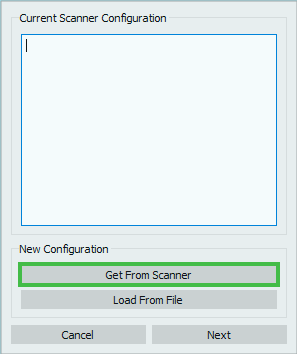
The first step of the process allows to set the configuration file of the Scanner. The Configuration file holds all the information on the various components of the user's specific scanner, therefore it is crucial for the functioning of the system.
To set it, make sure that the scanner is correctly connected and switched on and click on the Get From Scanner button to load it automatically.
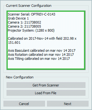
Once the file has been succesfully loaded, in the box will be shown:
- the scanner's serial number
- the scanner's components
It is also possible to load a configuration from and external file, using the button Load From File, though this kind of operation will be performed in very rare cases (for instance if Open Technologies had to modify the configuration file of the scanner and the internal file is no longer valid).
Click next in the dialog to follow with the configuration, click Cancel to abort.
System Calibration
The following step is the System Calibration starting with the Optical Head and then calibrating the movement system.
Head Calibration
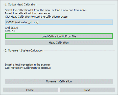
In order to proceed, the calibration kit .xml file must be loaded, by clicking on the buttonLoad Calibration Kit from File.
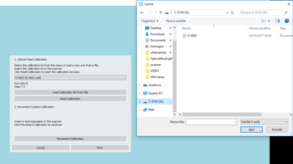
This .xml file can be found in the scanner's internal memory, identified by the computer as if it were a Usb flash drive.
NOTE: CHECK THAT THE NUMBER OF THE FILE AND THE NUMBER OF THE PLATE YOU HAVE IN THE ACCESSORIES BOX COINCIDE. IF THEY DO NOT CONTACT YOUR DEALER BEFORE CALIBRATING
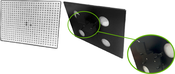
To insert the calibration plate in the scanner, detach the black support on the back of the plate simply by pulling, as it is held by magnets.
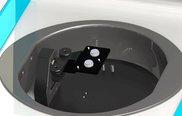
Release the two screws of the impression holder and insert the master support, tightening the screws as much as possible to fix it properly.
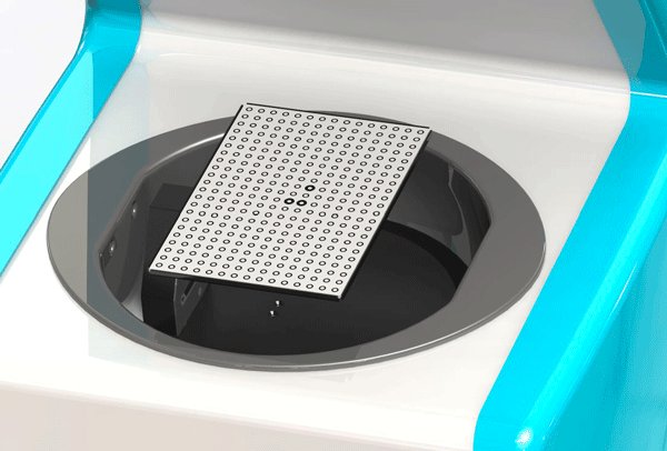
Place the calibration plate in the scanner taking care in positioning it keeping the part with one bold dot on the left and the side with two bold dots on the right.
Click the button Head Calibration to start calibration.
Movement System Calibration
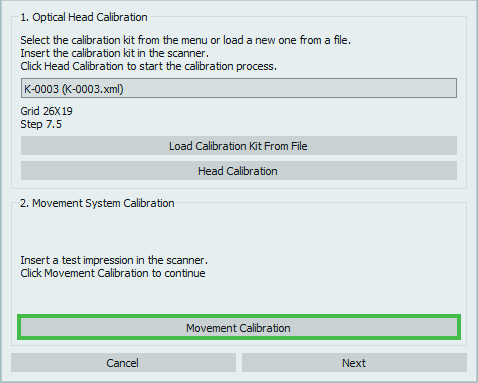
To follow with the movement system calibration insert an impression in the scanner as shown in the image and click on the button Movement Calibration. Remember that if you think of using the Triple Impression Module it is best to calibrate using the triple impression holder, so to have more precise plane cut settings.
Click next in the dialog to follow with the configuration, click Cancel to abort.
Set the Trimming
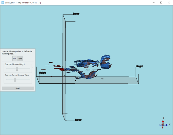
In this step the user can configure an automatic trimming that will automatically erase all the information located under the scan height plane for the individual impression and the planes to separate the elements for the triple impression holder.
Move the slider on the bar in the dialog to modify the scan height, taking particular care in not colliding with essential parts of the impression.
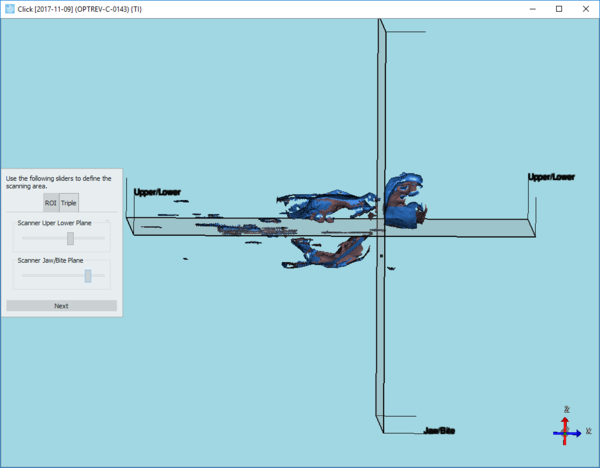
Then, if the Triple Impression Module is enabled in your license, click on the second tab Triple and move the sliders to establish the cut planes to separate the elements (upper from lower and individual from bite)
Click next in the dialog to end the first configuration procedure.
Access Calibration after first Configuration
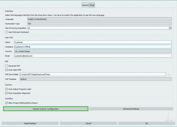
Should it be needed, it is possible to repeat the calibration even after the first configuration of the system simply by accessing the options in the welcome page using the Option Button .
In the first Option Page, General, simply click Restart Scanner Configuration to restart the calibration procedure.
